I have decided to have the car finished by a professional builder. So the last few weekends have been wrapping up the electrical system and some other things that I thought would be best for me to do. Then today I buttoned up the car, did an inventory of my remaining parts, and boxed everything up.
I'm expecting to have the car finished in time to do some fall driving this year.
Sunday, July 11, 2010
Monday, April 05, 2010
Moving along
It has apparently been 18 months since my last post. For those who were following expectantly, sorry about that.
I did eventually get the driver's side door on and fitted nicely. Then almost a year ago we had our third child, which slowed things down. But I'm back on it.
The rear hatch is fitted and installed. I had to cut the frame and reweld it a bit smaller, as most coupe builders have done. Installed the plexi to the frame with 73 little stainless button-head screws, each of which had to be marked, drilled, and tapped. There are 4 where the hole went through a weld and I broke either a drill or a tap. At those spots, I'm just going to cut a screw head off and glue it on for appearance.
I finished the passenger door last night, more or less. It was not a good fit, and I had to re-shape the inner curve of the door to match the curve of the body. I had to grind so much material out that I went through the fiberglass in spots, so then I cut away some, glassed in a patch, and filled. But my patch wasn't a great fit either, and I wound up grinding it down again far enough to make a tiny hole. But the door opens and closes solidly, so what remains is basically just cosmetic work.
The two really hard things left (I think) are getting the windows fitted and matching the nose to the body.
Sunday, November 16, 2008
Driver's door
Fun weekend. Spent the entire weekend on the driver's side door, and it isn't even close to finished. The door consists of a fiberglass "skin" over a steel frame.
I'm following the directions Mark Dougherty posted a while back instead of the FFR directions. First I trimmed the door skin to just fit the opening with tight gaps. This wasn't hard, but it was a little bit scary because I really didn't want to trim too much. I tried a couple of methods but what worked best was an angle grinder with a flap wheel. A light touch is essential!
Next I worked on the door frame. Got the welded bolts roughly parallel, ran a thread die over all of them to clean up the weld oxidation, and ground out the slots on the hinge arm for a "sloppy" (i.e., adjustable) fit. Opened up the factory door hinge cutouts (they were way too small) and installed the hinge and frame. Opened up the hinge cutouts some more to allow full motion. I also installed one shim washer under the upper bolt of the hinge mount bracket to get the angle of the frame a little better.
Then I installed the striker bolt, and adjusted the door frame to engage it. Perfect. But then I hit the first big snag.
Dougherty's directions call for sliding the door skin over the frame while the frame is already mounted and aligned on the latch. But the cutout on the front of the door is not large enough to fit the frame/hinge arm assembly as a unit. OK, fine. A bigger cutout is no big deal. 30 seconds with the Dremel and I have the skin on the frame, feeling like I'm a genius because fitting the doors is supposed to be really hard and I'm almost done.
Center the door skin on the body. Easy. Clamp the door to the frame. Oops. Not even close. The genius feeling is gone.
I have a few problems to work out. I need to extend the striker a little bit more, which should be easy. I need to shim the hinge forward on the frame a bit, which is also pretty easy. I need to grind out the slots on the hinge arm to angle the door up even more. No trouble. Shouldn't be more than 10-20 hours more work and I'll have a working door on the driver's side.
Thursday, November 13, 2008
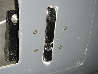
Directions for installing the fuel filler
1. Throw away the straight 2" rubber hose that you received with the kit. It is intended for the roadster and has no place on your coupe.

2. Buy the LeMans cap spacer from Mike Everson. You need it to keep the LeMans cap from hitting the body when it opens.
3. Buy NAPA part NBH 1046, 2" fuel filler hose with 45 degree bend.
4. Cut the fuel filler hard pipe. Leave most of the straight portion after the 90 degree bend on the lower piece. If you followed the manual and cut near the middle of this straight portion, you should have just barely enough straight pipe to make it work. The upper part needs to be cut down to just the last straight bit before the bend. Try to cut just behind the "bulkhead" in the tube with the spring door.

5. If you're a master craftsman like Russ, cut the tack welds on the fuel filler flange and reweld it closer to the end of the pipe. This not only looks cool but will save you the frustration of dropping the little white spacers about 10 times as you're trying to align the flange with the body and get the nuts on the screws. (Personally I didn't do this, because the thought of welding on thin pipe terrifies me.)
6. Position the fuel filler pipe in the hole from above. Mark and drill the body for the screws.
7. Get some #10 machine screws, washers, and nuts to replace the sheet metal screws or whatever they are in the kit. I just don't trust anything threaded into fiberglass.
8. Position the cap spacer on the body. Mark and drill the body for the screws. Slide the screws in to hold the spacer in position. From underneath, mark the filler flange screw holes on the spacer.
9. Drill recesses in the spacer for the filler flange screws. Don't go all the way through, but make sure they're large enough to contain the entire screw heads.

10. Screw the LeMans cap tightly onto its mounting flange. Keeping the spacer aligned with the screw holes, position the cap in the desired orientation over the spacer. Make registration marks on the spacer and the mounting flange.
11. Remove the cap from the mounting flange. Using the registration marks, mark the flange. Drill and countersink the flange.
12. Lubricate the filler pipe sections with vaseline to make the fitting much easier.
13. Cut down the hose to fit. I did it by cutting a little, trial fitting, cutting a bit more, etc.
14. Slide the hose clamps over the hose but do not tighten. You need everything sliding freely to geta the best alignment. Also, put the collar thingy on the lower pipe section.

15. Install the pipe/hose assembly and mount the flange to the body. This is where you get to drop those little white spacers over and over again. You can also drop the nylocks. They bounce and roll really well. (They're 10-32 thread, in case you've discovered just how well they bounce and roll.) Remember to install the ground wire on one of these screws. BTW, you could cut at least 1/4" off these screws to save yourself some work. 32 thread, so that's 8 full turns.
16. Tighten the band clamps and install the collar thingy. The bolt for the collar is metric something-er-other fine thread, if you've misplaced it like me.
17. Install the spacer and flange. Be sure the flange is in the same position as when you marked it.
18. Install the LeMans cap. It should tighten to just the right orientation.

Sunday, September 14, 2008
Nose work
At last posting, I had mounted the nose. But then I found that the striker brackets for the nose latches were about an inch too far back to line up with the cutouts on the nose. To move them, I had to take the whole body back off to get good access for cutting and welding. The welding was not very hard, and after a bunch of grinding and some fresh paint, the brackets look pretty good.


With the brackets moved forward, Stephanie and I remounted the body this weekend. It was a little bit easier this time around because I knew a few things to watch out for. But I think I'll need a crew of at least 5 to put it on when painted, to avoid scratching it up.
I put the nose back on and did some preliminary alignment. The driver's side is riding low but looks good front-to-back. The passenger side is too far back and too high. I think it is touching the radiator and the throttle, so there's going to be plenty of work getting it to fit right.


I got the nose mounted again and started working on the latches. It took quite a bit of grinding on the body to get the cutout right, and the latches themselves have mounting tabs that won't let the latch lever lie flush with the body. Fortunately it is soft metal and I was able to reshape the mounting tabs using my shop press.

The driver's side latch is mounted and flush, but the passenger's side still needs a lot of work on the body.

Monday, August 18, 2008
Pictures catchup, and nose mounted
Stephanie's brother Greg visited with his family last weekend. So I enlisted their help in getting the body onto the car. Went OK, but there are a bunch of places where it can get hung up on the frame. Scary to think what it will be like when it is painted and I care about it getting scratched.
Before

During:

Hmm. Must be hung up on the fuel tank:

Might as well throw the nose on for pictures:

Look Mom, I built a car!

OK, so at that point, the body looked like it was on, but it was actually riding very high on the driver's side. (As you can see from the rollbar in the photo.) And of course, the nose was just resting on the radiator and the body.
I finally tracked down the high left side to a spot on the bottom edge being hung up on one of the side body mounts, and it dropped into place nicely.
Next was the taillights, which double as the rear body mounts. Emmett was a huge help here, as I could not reach both sides of the taillights at once. I got them installed, and also got the body side mounts "done".

On to the nose. This was a fun little bit of measuring, fitting, drilling, saying oops, and so forth. I needed some help from Stephanie, as it is very difficult to be in two places at once. But I eventually managed to get the hinges together. There will be plenty of adjusting to do later.

So now you can open the hood:

Sunday, June 22, 2008
Electrical progress
Electrical system
- Connected all power wires at I*Squared power controller
- Routed headlight and highbeam wires
- Cut hole and installed grommet in tranny tunnel cover aluminum
- Attached dash ends
- Mounted dash
Subscribe to:
Posts (Atom)