Fun weekend. Spent the entire weekend on the driver's side door, and it isn't even close to finished. The door consists of a fiberglass "skin" over a steel frame.
I'm following the directions Mark Dougherty posted a while back instead of the FFR directions. First I trimmed the door skin to just fit the opening with tight gaps. This wasn't hard, but it was a little bit scary because I really didn't want to trim too much. I tried a couple of methods but what worked best was an angle grinder with a flap wheel. A light touch is essential!
Next I worked on the door frame. Got the welded bolts roughly parallel, ran a thread die over all of them to clean up the weld oxidation, and ground out the slots on the hinge arm for a "sloppy" (i.e., adjustable) fit. Opened up the factory door hinge cutouts (they were way too small) and installed the hinge and frame. Opened up the hinge cutouts some more to allow full motion. I also installed one shim washer under the upper bolt of the hinge mount bracket to get the angle of the frame a little better.
Then I installed the striker bolt, and adjusted the door frame to engage it. Perfect. But then I hit the first big snag.
Dougherty's directions call for sliding the door skin over the frame while the frame is already mounted and aligned on the latch. But the cutout on the front of the door is not large enough to fit the frame/hinge arm assembly as a unit. OK, fine. A bigger cutout is no big deal. 30 seconds with the Dremel and I have the skin on the frame, feeling like I'm a genius because fitting the doors is supposed to be really hard and I'm almost done.
Center the door skin on the body. Easy. Clamp the door to the frame. Oops. Not even close. The genius feeling is gone.
I have a few problems to work out. I need to extend the striker a little bit more, which should be easy. I need to shim the hinge forward on the frame a bit, which is also pretty easy. I need to grind out the slots on the hinge arm to angle the door up even more. No trouble. Shouldn't be more than 10-20 hours more work and I'll have a working door on the driver's side.
Sunday, November 16, 2008
Thursday, November 13, 2008
Directions for installing the fuel filler
1. Throw away the straight 2" rubber hose that you received with the kit. It is intended for the roadster and has no place on your coupe.

2. Buy the LeMans cap spacer from Mike Everson. You need it to keep the LeMans cap from hitting the body when it opens.
3. Buy NAPA part NBH 1046, 2" fuel filler hose with 45 degree bend.
4. Cut the fuel filler hard pipe. Leave most of the straight portion after the 90 degree bend on the lower piece. If you followed the manual and cut near the middle of this straight portion, you should have just barely enough straight pipe to make it work. The upper part needs to be cut down to just the last straight bit before the bend. Try to cut just behind the "bulkhead" in the tube with the spring door.

5. If you're a master craftsman like Russ, cut the tack welds on the fuel filler flange and reweld it closer to the end of the pipe. This not only looks cool but will save you the frustration of dropping the little white spacers about 10 times as you're trying to align the flange with the body and get the nuts on the screws. (Personally I didn't do this, because the thought of welding on thin pipe terrifies me.)
6. Position the fuel filler pipe in the hole from above. Mark and drill the body for the screws.
7. Get some #10 machine screws, washers, and nuts to replace the sheet metal screws or whatever they are in the kit. I just don't trust anything threaded into fiberglass.
8. Position the cap spacer on the body. Mark and drill the body for the screws. Slide the screws in to hold the spacer in position. From underneath, mark the filler flange screw holes on the spacer.
9. Drill recesses in the spacer for the filler flange screws. Don't go all the way through, but make sure they're large enough to contain the entire screw heads.

10. Screw the LeMans cap tightly onto its mounting flange. Keeping the spacer aligned with the screw holes, position the cap in the desired orientation over the spacer. Make registration marks on the spacer and the mounting flange.
11. Remove the cap from the mounting flange. Using the registration marks, mark the flange. Drill and countersink the flange.
12. Lubricate the filler pipe sections with vaseline to make the fitting much easier.
13. Cut down the hose to fit. I did it by cutting a little, trial fitting, cutting a bit more, etc.
14. Slide the hose clamps over the hose but do not tighten. You need everything sliding freely to geta the best alignment. Also, put the collar thingy on the lower pipe section.

15. Install the pipe/hose assembly and mount the flange to the body. This is where you get to drop those little white spacers over and over again. You can also drop the nylocks. They bounce and roll really well. (They're 10-32 thread, in case you've discovered just how well they bounce and roll.) Remember to install the ground wire on one of these screws. BTW, you could cut at least 1/4" off these screws to save yourself some work. 32 thread, so that's 8 full turns.
16. Tighten the band clamps and install the collar thingy. The bolt for the collar is metric something-er-other fine thread, if you've misplaced it like me.
17. Install the spacer and flange. Be sure the flange is in the same position as when you marked it.
18. Install the LeMans cap. It should tighten to just the right orientation.

Sunday, September 14, 2008
Nose work
At last posting, I had mounted the nose. But then I found that the striker brackets for the nose latches were about an inch too far back to line up with the cutouts on the nose. To move them, I had to take the whole body back off to get good access for cutting and welding. The welding was not very hard, and after a bunch of grinding and some fresh paint, the brackets look pretty good.


With the brackets moved forward, Stephanie and I remounted the body this weekend. It was a little bit easier this time around because I knew a few things to watch out for. But I think I'll need a crew of at least 5 to put it on when painted, to avoid scratching it up.
I put the nose back on and did some preliminary alignment. The driver's side is riding low but looks good front-to-back. The passenger side is too far back and too high. I think it is touching the radiator and the throttle, so there's going to be plenty of work getting it to fit right.


I got the nose mounted again and started working on the latches. It took quite a bit of grinding on the body to get the cutout right, and the latches themselves have mounting tabs that won't let the latch lever lie flush with the body. Fortunately it is soft metal and I was able to reshape the mounting tabs using my shop press.

The driver's side latch is mounted and flush, but the passenger's side still needs a lot of work on the body.

Monday, August 18, 2008
Pictures catchup, and nose mounted
Stephanie's brother Greg visited with his family last weekend. So I enlisted their help in getting the body onto the car. Went OK, but there are a bunch of places where it can get hung up on the frame. Scary to think what it will be like when it is painted and I care about it getting scratched.
Before

During:

Hmm. Must be hung up on the fuel tank:

Might as well throw the nose on for pictures:

Look Mom, I built a car!

OK, so at that point, the body looked like it was on, but it was actually riding very high on the driver's side. (As you can see from the rollbar in the photo.) And of course, the nose was just resting on the radiator and the body.
I finally tracked down the high left side to a spot on the bottom edge being hung up on one of the side body mounts, and it dropped into place nicely.
Next was the taillights, which double as the rear body mounts. Emmett was a huge help here, as I could not reach both sides of the taillights at once. I got them installed, and also got the body side mounts "done".

On to the nose. This was a fun little bit of measuring, fitting, drilling, saying oops, and so forth. I needed some help from Stephanie, as it is very difficult to be in two places at once. But I eventually managed to get the hinges together. There will be plenty of adjusting to do later.

So now you can open the hood:

Sunday, June 22, 2008
Electrical progress
Electrical system
- Connected all power wires at I*Squared power controller
- Routed headlight and highbeam wires
- Cut hole and installed grommet in tranny tunnel cover aluminum
- Attached dash ends
- Mounted dash
Saturday, June 21, 2008
New format, and new progress
It's been a while. I'm going to try out a new format for these blog posts. I hope will help me just dump the information on here without spending a lot of time thinking about what to write.
Footbox electrical panel
Footbox electrical panel
- Fabricated and installed aluminum electrical panel to fit under access panel. Original panel was not well positioned for access.
- Installed terminal strips and fuse holder in new electrical panel.
- Removed and replaced steering column to resolve u-joint that had slipped and was binding.
- Tightened all set screws.
Monday, March 31, 2008
Weekend progress
Good weekend for working on the coupe. First, I changed the oil, which had been contaminated with coolant during the intake manifold excitement. It came out looking creamy. I guess the oil has enough detergents to keep the water in suspension rather than letting it settle out.
Next, I installed the battery in my new battery frame. The battery is still located in the same location under the trunk and just behind the differential. After all the trouble I went through building my aluminum battery box, I just wasn't happy with it. I didn't like the fact that it was held in by aluminum rivets loaded in shear. The new frame is welded steel, and it is very strong. A little gloss black spray paint to match the power coating and hide my ugly welds and it looks great too. I should have some pictures, but I don't.
I got it to idle by adjusting the throttle stop screw. Seems to be OK now. The timing was dead on at 10 BTDC. So I guess I did it right when I set the distributor.
Then the big task was an access panel for the driver side footbox. I have mounted some terminal strips, a fuse, etc. up there, so I needed access. I really liked Detroit Kim's access panel on the ffcobra forum. So I attempted to emulate. Mine isn't as good, but it isn't too bad, either:

The rivets hold a clip on the back side that secures the rear part. I'll put a few rivnuts top, bottom, and front to secure it. But the back will actually slide under the body a little bit, so the clip will avoid some inaccessible fasteners.
Sunday, March 09, 2008
First start!
I started the coupe today. Here's the unedited video of the first time I pushed the starter button. For the full experience, be sure to view this with good speakers and the volume loud enough to make small children cry. (Luke cried.)
It didn't want to idle, probably because the timing was way off.
It almost didn't happen. When I filled the motor with coolant, it just poured out the back, coming from between the intake manifold and the head. So on Saturday, we pulled the intake manifold and it became obvious what the problem was. The heads are 289 heads, but the intake is from a 302. The 289 heads are actually a little bit shorter than the 302, with narrower water passages. The result is that the water passage at the rear of the drivers side actually overhangs the rear of the head!
So I used some J B Weld to narrow the water passages in the intake, new gaskets, and plenty of silicone to make the seal. But when we got it all buttoned back up, it still leaked like crazy. I had managed to get a wire pinched under the rear of the intake. Doh! Pulled the intake again (intact) and replaced the gaskets again.
In between, I also wired the dash, tightened up the wiring under the car, attempted to set the timing, and did a million other things.
I have several issues to resolve. There's a tiny fuel leak. The timing is way off, or perhaps there's some other reason why it would barely idle. And the battery is junk. (It's the donor Mustang battery. I didn't want to buy a new battery until I was ready to use it.)
Monday, March 03, 2008
Wiring coming together
I continued working on the wiring this weekend.
The I-Squared was having some trouble with my fan. Seems that the initial current draw for the electric fan was too high for the I-Squared. One option would be to dedicate two separate circuits to the fan. Another would be to build some kind of inrush limiter circuit, either a fancy active circuit or an inrush limiting thermistor. But in the end, the simplest thing was to just buy a $35 fan control module from AutoZone and skip the I-Squared on this circuit. I got it mostly wired up. The fan operates thermostatically with a probe in the radiator. I also have an override switch to turn it on, and there's one more wire I need to connect so that the A/C also turns it on.
Then I turned my attention to the EFI harness. I spent a long time tracing and labeling the wires on the three connectors that go to the Mustang body harness. Those have things like the gauge wires and power inputs on them. I nearly drove myself nuts with a light green/purple wire that came off one of these and just seemed to go nowhere. Finally traced it to a plug labeled "To Heater". I still don't know what it is, but I know where it goes.
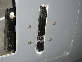
I removed the EEC power relay from the harness. I'm running my power from the I-Squared, so there was no need for this relay. But I decided I do still want a fuel pump relay so that the computer can control the fuel pump. I also decided to put the inertia switch directly on the fuel pump circuit instead of on the I-Squared control circuit. If I crash and that switch opens, I want the fuel pump off no matter what. So I found a spot near the fuel filler to mount the relay and switch, and I'll make an access panel from the trunk area.
I'd have finished up the EFI wiring yesterday, but I took most of the day off from the car because it was Stephanie's birthday. So I still have a few connections to make and wires to run, but it should all come together soon.
[This post should have been published 3/3, but Blogger was crashing on me.]
The I-Squared was having some trouble with my fan. Seems that the initial current draw for the electric fan was too high for the I-Squared. One option would be to dedicate two separate circuits to the fan. Another would be to build some kind of inrush limiter circuit, either a fancy active circuit or an inrush limiting thermistor. But in the end, the simplest thing was to just buy a $35 fan control module from AutoZone and skip the I-Squared on this circuit. I got it mostly wired up. The fan operates thermostatically with a probe in the radiator. I also have an override switch to turn it on, and there's one more wire I need to connect so that the A/C also turns it on.
Then I turned my attention to the EFI harness. I spent a long time tracing and labeling the wires on the three connectors that go to the Mustang body harness. Those have things like the gauge wires and power inputs on them. I nearly drove myself nuts with a light green/purple wire that came off one of these and just seemed to go nowhere. Finally traced it to a plug labeled "To Heater". I still don't know what it is, but I know where it goes.
I removed the EEC power relay from the harness. I'm running my power from the I-Squared, so there was no need for this relay. But I decided I do still want a fuel pump relay so that the computer can control the fuel pump. I also decided to put the inertia switch directly on the fuel pump circuit instead of on the I-Squared control circuit. If I crash and that switch opens, I want the fuel pump off no matter what. So I found a spot near the fuel filler to mount the relay and switch, and I'll make an access panel from the trunk area.
I'd have finished up the EFI wiring yesterday, but I took most of the day off from the car because it was Stephanie's birthday. So I still have a few connections to make and wires to run, but it should all come together soon.
[This post should have been published 3/3, but Blogger was crashing on me.]
Monday, February 11, 2008
First start scheduled
I was feeling pretty good about my progress yesterday. So much so that I invited my dad out for the weekend of March 8, for the first start. I should be able to go-kart it sround the neighborhood if it isn't snowy. So now I'm in a serious push to get this thing done.
But first, a picture. My brother points out that there have not been any long shots of the entire car for a while. Partly that's because it is hard to get such a shot in the shop, and partly it is because such a shot would let you see the giant mess that makes it so hard to get such a shot. But anyway, here are a couple:


I spent a bunch of time this weekend re-doing my fuel lines, because I had followed the build manual and bent them up in front of the passenger footbox. Now they hug the 4" tube all the way to the front of the engine, which is where the stainless hard lines come down. I have no idea why the build manual suggests that. I'm a short piece of hose and two hose clamps away from completing the fuel system.
What's left for the next few weeks is some electrical, seats, intake, O2 sensors, and the removable steering wheel. I'm going to leave the steering wheel for now because I can always slap the fixed wheel in place. I figured I just need 4 power circuits on the electrical for a go-kart. (Ignition, fuel pump, starter, and fan) So I ran 4 wires. I don't want to get cocky, but it seems like electrical is going to be very simple with the I*Squared system. Here's my trunk-mounted power box.

And finally, catching up from a while ago, here are those cool Russ Thompson pedals. I think I need some kind of stop to keep the clutch from coming up so high.

That's it for now. I had a couple more pictures, but Blogger isn't cooperating.
Tuesday, January 29, 2008
Still no pictures
I did some work on the car this past weekend, but didn't take any pictures. So the dilemma is whether to post here or not. I'm going with a post, for the sake of recording the history of my progress. I can always come back and add a picture later if I take one.
First I got my Russ Thompson pedal pads installed. These are aluminum plates that go on the brake and clutch pedals to make them match the very nice Russ Thompson gas pedal that I got. They look much better than stock. The directions were so cute, too. They noted that the original steel pedal would interfere with the rubber grommets in the pedals, so you'd have to grind them down a bit. As though there were parts of this car that don't need a grinder for installation.
Then I finished up my cooling system, or at least the water-carrying parts thereof. (The electric fan still needs to be hooked up.) I bypassed the heater for now, because it was slowing me down just thinking about it. The car isn't likely to get much winter use anyway.
Monday, January 14, 2008
Freezing my butt off
It's cold in the shop. So cold that I've been a little worried about my beer and soda in the shop fridge. Any idea how cold a bottle of beer can get before it blows up? I'm not sure, but it has been down to 25 on the thermometer out there and they're still intact. The fridge might be warmer than the rest of the shop. Anyway, 25 is cold enough that you really can't handle metal tools without gloves, and it isn't any fun to lie down on the concrete floor.
I got out and did a little work this weekend anyway. I got my front cover bolted back on again, along with the thermostat housing. I drilled and tapped the thermostat housing for the fan switch, and it seemed to go pretty well even though I did not have the correct 37/64" drill bit. I attached the small coolant hoses (heater loop, bypass, heater return), routed the positive battery cable from the trunk area to the starter relay, and hooked up the transmission end of the speedometer cable. Just little things here and there. I think next up is radiator plumbing.
Catching up from last week, I got the pedal bender tool from Roy and put a little space between my brake and accelerator. Even so, I think I'll need to drive in narrow shoes. The clutch can't really go any further left because of the frame tube. I could potentially open up a little more space to the right of the accelerator by customizing the aluminum there.
Subscribe to:
Posts (Atom)