I didn't get so much done on the car this weekend. Yesterday I spent most of the day working on Stephanie's laptop. The screen had stopped illuminating, and I eventually tracked down the problem to th ribbon cable that connects the screen. I was close to buying a new computer, but in the end, I fixed it with parts on hand.
Last night I mounted my roll bar switch panel. I saw one like it on another coupe and I just had to have it. I'll try to get a picture up later.
Today I cut the dash for the larger vintage gauges. It wasn't as hard as I thought it might be, but it took a long time. The aluminum is easy enough to cut, but I was trying to be very careful and not cut outside the lines.
Sunday, October 21, 2007
Sunday, October 07, 2007
Radiator and battery
I've been doing quite a bit of work on the car, but I haven't been blogging all of it. Two weeks ago, I made myself a battery box. It works OK, but the battery fit is maybe a little tighter than what I intended. Here it is under construction.

Here's a picture of the casting number on my motor. I figured I'd better have a picture of this when it came time to register the car, since the year of the motor is important. So I snapped this before installing the starter, which makes it impossible to see. 5K1 means that my motor was cast on October 1, 1965. Happy 42nd!

Last night I put together a to-do list of everything I need to do to get to the go-cart stage. The list had 59 items, ranging from filling the motor with oil to installing my seat. I went out and got 3 of those items done today, most notably mounting the radiator. I think it is too high, and will hit the nose. But I'll worry about that when I'm fitting the nose.

If you're reading these posts, please add some comments. I sometimes wonder if I'm just talking to myself.
Saturday, September 15, 2007
Firewall modification
The A/C kit I have from North Racecars puts the evaporator behind the dash on the passenger side. Only there isn't enough room between the dash and the firewall to mount the evaporator. So you have to modify the firewall to accommodate. I knew this, so it is a complete mystery to me why I decided last December that I could go ahead and rivet the firewall in place. But there it was, and it needed to come out.
Most of the rivets were simple to drill out. A good drill goes through aluminum rivets like butter. But with the engine in place, a few were in tight spots, so tight that I couldn't even get my right-angle adapter on them. A chisel solved that problem. Knocking the head off an aluminum rivet with a chisel is almost as easy as drilling it out.
With the firewall out, I was able to cut it and bend it:


Then I made two triangular end pieces, using my brand new bending brake from Harbor Freight:


Then I fitted them into place, drilled for rivets, and installed with Clecos.


This was my first sheet metal fabrication, and I think it turned out great. It makes me look forward to some of the other fabrication I need to do. (Battery box, I-Squared controllers, maybe more.)
Most of the rivets were simple to drill out. A good drill goes through aluminum rivets like butter. But with the engine in place, a few were in tight spots, so tight that I couldn't even get my right-angle adapter on them. A chisel solved that problem. Knocking the head off an aluminum rivet with a chisel is almost as easy as drilling it out.
With the firewall out, I was able to cut it and bend it:
Then I made two triangular end pieces, using my brand new bending brake from Harbor Freight:
Then I fitted them into place, drilled for rivets, and installed with Clecos.
This was my first sheet metal fabrication, and I think it turned out great. It makes me look forward to some of the other fabrication I need to do. (Battery box, I-Squared controllers, maybe more.)
Sunday, September 09, 2007
Ignition system
Today I mounted my MSD ignition box and ignition coil. The ignition box was straightforward. I put it on the x-brace in the front of the engine bay:

The ignition coil was a little bit trickier. The various locations I could find to mount it using the Mustang bracket suffered from various problems: Too close to the exhaust, possibly interfering with the nose, etc. So I ditched the Mustang bracket and made my own out of some angle aluminum. the new mount bolts to the head, next to the A/C compressor:


The ignition coil was a little bit trickier. The various locations I could find to mount it using the Mustang bracket suffered from various problems: Too close to the exhaust, possibly interfering with the nose, etc. So I ditched the Mustang bracket and made my own out of some angle aluminum. the new mount bolts to the head, next to the A/C compressor:


Sunday, August 12, 2007
Engine accessories
Lots of progress today. Got the pulleys on the crankshaft and water pump, then put on the alternator, tensioner, and A/C compressor. The compressor mounts right where the power steering pump was, but it is a bit smaller. So I need a somewhat shorter belt. But it all went much easier than I was fearing it would.
On to the distributor. Needed to put the engine at top dead center first. A quick look at the damper had me worried. There are two sets of degree markings, and two distinct pointers. So I decided to pull out the spark plug to be sure. That's when I found out that the exhaust header flange made it impossible to put a socket on the spark plug. Nice.
Now if you go back and read the last post, you'll realize why I was really unhappy about having to pull the headers off again. But the only way I was going to get that spark plug off was to do a little grinding on the header flange. So off it came. Good thing I decided to check. TDC was not where I expected it based on the pointer.

This is starting to look like it could move a car! To get to go-kart stage, I still need to do the following:
Radiator and hoses
Ignition system (coil, MSD box, wiring)
Ignition switch
Computer and associated wiring
Fuel lines
Battery
Fill fluids
Fill and bleed brakes
Approximate alignment
That's still a lot, but it is starting to seem within reach.
Tuesday, June 26, 2007
Starting to look like a motor
The intake and exhaust make it look much more like a motor. Intake was pretty easy once I figured out that I was trying to put the throttle body in upside down. Which is to say right side up. I think my polymer intake is lower than the stock upper, causing the throttle cable bracket to interfere with both the fuel rail and the valve cover when installed in the normal way. I found incontrovertable evidence that the throttle body was previously installed upside down, so I put it back that way. Looks OK, but I'm a little worried about the throttle bracket and hood clearance.
I was going to try to finish up my fuel lines, but realized that I needed to know exactly where the right-side exhaust was going to be first. So I put that in. Now I know why everybody was chatting about how to tighten the exhaust header bolts. None would take a socket. Some were easy with a box-end wrench. Some required an open-end wrench, because they're so close to the pipe that you can't even get a box-end around them. One was so close to the pipe that the open-end wrench had well under 60 degreees of travel. That one is just not going to be tight.
I was going to try to finish up my fuel lines, but realized that I needed to know exactly where the right-side exhaust was going to be first. So I put that in. Now I know why everybody was chatting about how to tighten the exhaust header bolts. None would take a socket. Some were easy with a box-end wrench. Some required an open-end wrench, because they're so close to the pipe that you can't even get a box-end around them. One was so close to the pipe that the open-end wrench had well under 60 degreees of travel. That one is just not going to be tight.
Monday, June 11, 2007
Intake manifold installed
Well, that was easy. When I pulled the manifold back off, I found that the broken bolt still had about 2 threads sticking up above the head, and was not tight at all. So I was able to remove it with nothing but my fingers. Close inspection revealed slight but distinct necking of the bolt, on the thread right below where it broke. There's no way I put enough torque on it to create any necking, so it had to have been overtorqued previously. That's a little scary. I took a look at the other bolts, and they looked OK, though I didn't reuse any of them.
Hmm. I forgot to publish this post. Oh well, here it is.
Hmm. I forgot to publish this post. Oh well, here it is.
Monday, June 04, 2007
Restarted, I hope
I got e-mail last week from a guy named Warren, of Heber. He is thinking about building a coupe and wanted to come by, look at the chassis, sit in it, etc. So on Saturday I went out and spent a couple of hours cleaning up my shop and getting everything looking good. Show-and-tell went great, and the clean shop got me inspired to do some work on the cars.
First, of course, was swapping the winter tires back to the summer tires on the van. Then I fixed the coolant leak in my RX-7. (I hope!) But finally, I went to install my intake manifold, which has just been sitting on top of my motor since I did the cam swap.
The intake manifold has 12 bolts, and you're supposed to tighten them in a specific sequence, first to 8 ft-lbs, then 16, then 22-24. I don't think my torque wrench is trustworthy at 8 ft-lbs, but I just went snug, then 16 then started to do 24 and SNAP!
One of the Grade 8 manifold bolts broke. Brittle failure, on a 5/16" bolt at something less than 24 ft-lbs. Weird. OK, let's do a little calculation. A 5/16" bolt should have a stress area of .0524 in^2. Grade 8 means minimum tensile strength of 150,000 psi. So that's a maximum load of 7860 lbs. Now according to my sources, a torque of 25 ft-lbs on a dry 5/16"-18 bolt gives a clamp load of 4720 lb. But assume my torque wrench is off by 20% to give and the threads were lubricated by some residual oil. Now we've got 7550 lbs. Hmm. That's getting close.
Well, now I'm paranoid about the other bolts, so I ordered a complete set. Haven't pulled the manifold back off, so I'm not sure exactly how difficult it is going to be to remove the broken bolt. But I'm hoping that it should come out pretty easily, since it's not like a bolt that was frozen and snapped off when I was trying to remove it. It shouldn't even be tight in there.
Wednesday, January 31, 2007
Delayed
I can't believe it's been two months since my last post. But anyway, here's the story.
First there was Christmas. We had my whole family out to Utah, and there was a bunch of prep that went into it. Painted a bathroom, changed out some fixtures, etc.
Then on Jan 1, I went skiing. Started out as a great day, until I fell. Tore my ACL. Major bummer.
Jan 17 was surgery to reconstruct my ACL, with a hamstring tendon autograft. Ouch.
So now I'm two weeks past surgery, and working hard on my rehab. I'm not working on the car at all. I hope to get back to it in another few weeks, but it just isn't a priority right now.
Monday, November 27, 2006
Motor!
(15? hours since last post, 69 hours total)
We'll call it 15 hours. I don't really know how accurate that is, since I've just been spending an hour here and there for the last week. I finished the cockpit rear aluminum. Drivers side was great. Passenger side didn't want to line up, so I had to trim it, but it is in too.
Then yesterday I tried to put the motor in. Got myself a load leveler from Harbor Freight. ($20) This is a device that lets you change the support point of your hanging load so that it tips, so you can drop the transmission tail down into the transmission tunnel, then flatten it out as you lower the motor.
Attempt #1: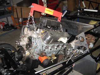
This was the first attempt. At about this point, it became clear that I needed to have the crank on the other end of the load leveler, because it was going to hit the firewall.
Attempt #2:
No good pictures of this one. I tried the same thing but with the crank at the other end. This time, I got the motor down within a couple of inches of the motor mounts, but had to pull it back out because the load leveler hit the firewall crosspiece.
Attempt #3:
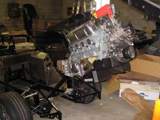 I took the upper intake manifold off the motor to get a little more room. I thought that if the load leveler was where the intake normally goes, I'd clear the firewall. It almost worked. It was so close that I could actually put the motor mount bolts onto the motor mount brackets, but I just couldn't drop them into the slots.
Attempt #4:
Went without the load leveler this time, with just a chain on the motor. That made it difficult to get the transmission tail up over the 4" round crosspiece in the transmission tunnel. But it eliminated all the clearance issues at the firewall. I used two jacks, a furniture dolly, a 2x4, and some wooden shims to maneuver the transmission in. The result? Success!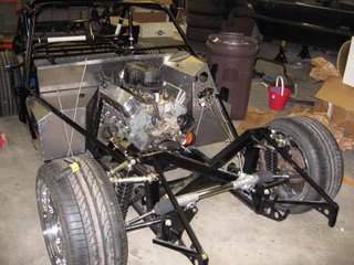
We'll call it 15 hours. I don't really know how accurate that is, since I've just been spending an hour here and there for the last week. I finished the cockpit rear aluminum. Drivers side was great. Passenger side didn't want to line up, so I had to trim it, but it is in too.
Then yesterday I tried to put the motor in. Got myself a load leveler from Harbor Freight. ($20) This is a device that lets you change the support point of your hanging load so that it tips, so you can drop the transmission tail down into the transmission tunnel, then flatten it out as you lower the motor.
Attempt #1:

This was the first attempt. At about this point, it became clear that I needed to have the crank on the other end of the load leveler, because it was going to hit the firewall.
Attempt #2:
No good pictures of this one. I tried the same thing but with the crank at the other end. This time, I got the motor down within a couple of inches of the motor mounts, but had to pull it back out because the load leveler hit the firewall crosspiece.
Attempt #3:
 I took the upper intake manifold off the motor to get a little more room. I thought that if the load leveler was where the intake normally goes, I'd clear the firewall. It almost worked. It was so close that I could actually put the motor mount bolts onto the motor mount brackets, but I just couldn't drop them into the slots.
Attempt #4:
Went without the load leveler this time, with just a chain on the motor. That made it difficult to get the transmission tail up over the 4" round crosspiece in the transmission tunnel. But it eliminated all the clearance issues at the firewall. I used two jacks, a furniture dolly, a 2x4, and some wooden shims to maneuver the transmission in. The result? Success!

Sunday, November 19, 2006
Footboxes
(7 hours since last post, 54 hours total)
Completed the footboxes today. Actually, the driver's side is not installed, but all the panels are drilled and ready to go in, and that is by far the hard part.
But first, to catch up on photos:
Completed the footboxes today. Actually, the driver's side is not installed, but all the panels are drilled and ready to go in, and that is by far the hard part.
But first, to catch up on photos:
 The pedals as they'll look inside the car, more or less. The accelerator is the very nice Russ Thompson version. I discovered that the placement of this pedal is incompatible with the cruise control switches on the Mustang pedal box. Fortunately, I wasn't planning to use the cruise control anyway.
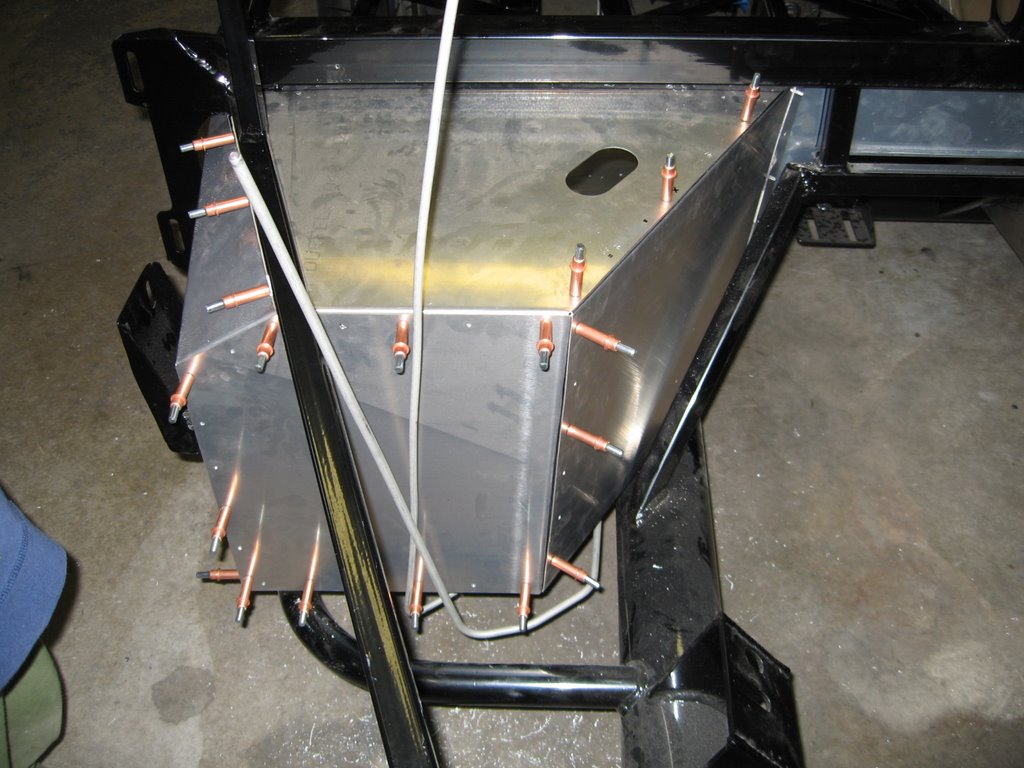 Passenger side footbox, as completed with Clecos. Took almost all of my 50 Clecos to hold it together like this.
 Passenger footbox from the inside. Note all the aluminum debris from drilling the panels. This is when it is really good to have a helper.
 Here's Emmett cleaning up all the drill debris. He's very enthusiastic about this task. I have to make sure to pick up anything that I don't want to fish out of the vacuum later.
The passenger footbox is complete. Drilled, bonded, and riveted. It's surprisingly solid. When the panels are anchored by a few screws at the corners, they're disturbingly flexible. When they're finished with rivets along each edge, they form a very rigid box.
The Drill Doctor that my Dad got me for Christmas last year has been extremely important. After drilling enough holes, I'll find the bit working very slowly even on the aluminum. A quick trip through the sharpener yields one of two results. Either the bit becomes completely useless, or it becomes fantastically sharp. I haven't figured out what creates the inconsistency, so I just sharpen again if necessary.
I'm taking 5 days off work, plus the Thanksgiving holidays, so I hope to get a lot done on the car. Ideally, I'd like to finish the aluminum and install the motor and transmission.
Monday, November 13, 2006
Aluminum panels
(Roughly 7 hours since last post, 47 hours total)
Some lost time from the last time I posted. This is my best guess. I spent two hours on the car last night.
I've started the aluminum panels that form the interior of the car.
Each piece is to be bonded to the frame with silicone sealant (to prevent rattles) and then riveted. Since most of the panels came mounted on the frame in the first place, I did at least mark the panels where they meet the frame. So for each piece, the procedure is something like this:
1. Compare the piece to the intended location to verify markings and perform a sanity check.
2. Drill panel for rivets. Mostly these are on 2-inch spacing, in straight lines. Drilling the aluminum is quick and easy.
3. Install the panel in place
4. Drill two or three holes in the frame, placing a Cleco in each. Clecos are temporary fasteners that hold like rivets, and they're perfect for this application.
5. Drill the remaining holes in the frame. The frame is steel, and though it isn't really hard steel, it isn't exactly quick to drill.
6. Remove the Clecos and remove the panel.
7. Apply silicone to the frame.
8. Re-install the panel using a few Clecos.
9. Rivet all the holes that don't have a Cleco in them.
10. Remove the Clecos and finish riveting.
So far I've done 5 panels. Two are the large floor panels, which have more rivets than anything else except maybe the trunk floor. The other 3 are small: The transmission tunnel front wall, the driver footbox floor, and the driver footbox front wall. That's a lot of drilling.
Oh, and I also installed the Russ Thompson gas pedal. Without the throttle cable yet, there's not much to it. It looks great.
I have some pictures, but they're not on the computer yet.
Wednesday, November 01, 2006
Pedals
(2 hours this weekend, 40 hours total)
I installed the pedal box (brake and clutch) this past weekend. Went in pretty easily once I got all the parts together The trick was in getting the brake pushrod out of the Mustang brake booster.
I had started this process a long time ago, when I first pulled the booster out. The build manual says something about crushing the plastic part in a vise and then pulling the pushrod out. Fine, but the studs were in the way of crushing it. So I did some cutting and drilling and whatnot and broke off the plastic part pretty good, but the pushrod did not come out. So I set the thing aside until this past weekend.
This time, I read up on the process on FFCobra.com. The consensus was to just keep breaking plastic with a chisel and a BFH. (That is, a hammer.) So I did that, and got the pushrod out. Then you're supposed to remove the aluminum fitting from the pushrod by heating it with a torch. Sounds like fun. I heated that thing up really good, then pulled on the fitting with some pliers.
Now the thing you need to know at this point is that the aluminum fitting is connected to the pushrod by means of a rubber bushing. You can't just cut the bushing, because it is inside the fitting. By heating it, what you're trying to do is melt the rubber, so the fitting slides right off.
I did more than melt the rubber. When the fitting came off, the rubber was so hot that it ignited, and I had a flaming pushrod in my vise, and a flaming fitting in my pliers. I just wish I had a picture of it.
Next up would have been the gas pedal, but after a little trial fitting, I decided to ditch the donor pedal. It just doesn't fit right, and the proposed modification from the build manual would result in the pedal pad being at a strange angle and the lever arms being all wrong. So I bought a Russ Thompson pedal from Breeze. Should have it in a couple of days, hopefully for installation this weekend.
Sunday, October 22, 2006
Brake plumbing complete
(2 hours yesterday/this morning, 37 hours total)
Finished up the brake line plumbing. Starting from the master cylinder:
Simplest possible brake setup. Cobra master cylinder with no proportioning valve.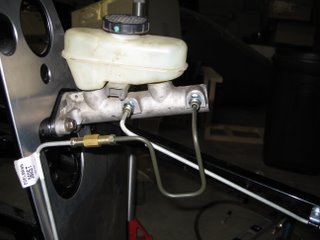
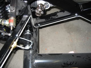
Left front on a T fitting, with the line continuing to the right front.
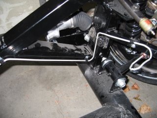
Right front.
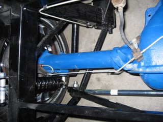
Left rear. I need to figure out how to anchor these lines on the axle.
Right rear.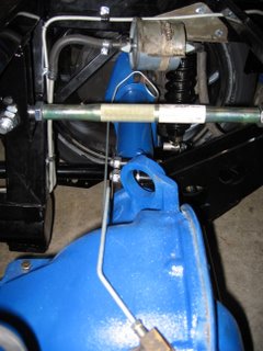
Finished up the brake line plumbing. Starting from the master cylinder:
Simplest possible brake setup. Cobra master cylinder with no proportioning valve.

Left front on a T fitting, with the line continuing to the right front.
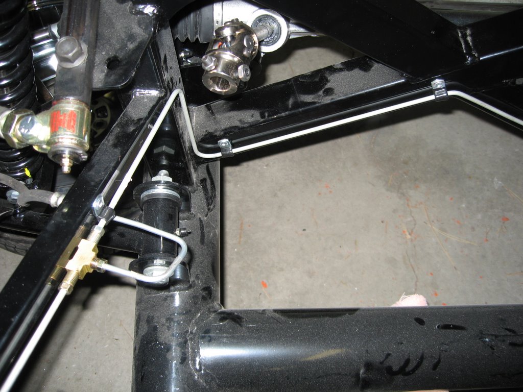
Right front.
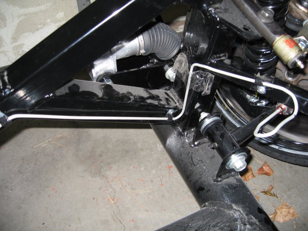
Left rear. I need to figure out how to anchor these lines on the axle.

Right rear.

Monday, October 16, 2006
Brake lines
(5 hours this weekend, 35 hours total)
Hard to get a lot of time for the car with a new baby. But I did put in some work on my brake lines this weekend.
I mounted the brackets that hold the flexible lines on the rear end, then fabricated the rear end hard lines. I should get a picture of this up, because I think it looks pretty cool. The only thing that I don't like is that they don't match. On the right side I have a loop in the line to provide for some flexibility in the line. But bending the loop was a lot of trouble, and it made it tough to put the wrench on the flare nut. So on the left side I went with an S bend.
I also mounted the master cylinder and completed the rear brake circuit. I don't know how Factory Five thinks you're going to get the brakes connected with the lines they provide. They're just too short! So now I have a 1-foot extension on the rear brake line, which is a different color, and the union is visible. Maybe I'll go back and do it again. But only if it leaks.
Finally, I mounted the small brackets that hold the flexible lines from the front brakes. But now I think I did it wrong, and I'll either need to remount them or cut the aluminum panel in the wheel well. But with the way they're supposed to be mounted I think the left side flexible line just isn't going to be long enough. I guess I need to locate the panel and figure out what to do next.
Wednesday, September 20, 2006
Mounted fuel tank
(1.5 hours, 30 hours total)
I installed the fuel tank today. Nothing too exciting, though it was yet another part that I got to hit with a hammer. This time, the hammer was to straighten out some bent edges that were preventing a good fit.
The return fuel line is now fully connected. The supply line is not properly clipped to the fuel filter. I think I need new clips, and I definitely need a new fuel filter.
I couldn't bring myself to spend time cleaning and painting a fuel tank that is going to be completely hidden from view in the finished car. A lot of Cobra builders seem to paint everything, and I certainly did paint my rear end, spindle adapters, etc. But the fuel tank? That's just going too far.
Friday, September 15, 2006
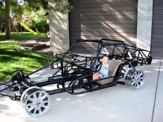
Rolling
(3 hours Wednesday/Thursday, 28.5 hours total.)

She's a roller. Not much real progress, but I got the rear LCA bolts replaced, put the spindles back on, connected the tie rods, and put the wheels on. I spent over an hour just replacing one little bolt on the forward arm of the upper arm bracket of the 3-link. It did not want to line up. I finally made myself a custom alignment tool out of a second bolt. I cut the head off, and tapered one end with a grinder. One day I hope to install some part of the car without using a hammer.

She's a roller. Not much real progress, but I got the rear LCA bolts replaced, put the spindles back on, connected the tie rods, and put the wheels on. I spent over an hour just replacing one little bolt on the forward arm of the upper arm bracket of the 3-link. It did not want to line up. I finally made myself a custom alignment tool out of a second bolt. I cut the head off, and tapered one end with a grinder. One day I hope to install some part of the car without using a hammer.
Tuesday, September 12, 2006
Spindles and studs
In my last post, I mentioned the bump steer studs that were left in the spindles. I now feel certain that the reason he left these in is that he couldn't get them out.
Well, they're out. Or more accurately, they're gone. Both were removed destructively. The first one was tough. I tried the standard technique of hitting the spindle with a big hammer and had no success. I then tried hanging a 5-gallon bucket of water from the stud (to get some tension on it) and hitting the spindle with a hammer, with no success. Then I drilled a 3/8" hole from the top clear through the tapered section, to release the pressure on the taper, and tried hitting it some more. No success. Finally I used a Dremel with a cutoff wheel to cut a groove in the stud just below the spindle. I stuck a chisel in the groove and hit it hard with a hammer, and the stud popped out.
On to the left side. Basic techniques again failed. I tried the drill and chisel technique that worked for the first one, with no success. I cut the bottom part of the stud off so I could get an impact socket on the hex section, and tried to break it loose with an impact wrench. The stud sheared off where I had cut the groove. (Note that it was hollow at this point from the drilling!)
With no way to pull on the stud, I started trying to figure out how to push on it. My big sledge (on a punch set in the hole) did nothing. I got a 12-ton hydraulic press from Harbor Freight and tried that, but the remaining portion of the stud above the spindle just crushed, since it was just a thin shell. So I drilled out the top of the stud to 1/2", matching the top part of the spindle hole, and drilling about half way through. Then I flipped it over and hollowed out the bottom part of the stud to just a thin shell of the taper, using a tungsten carbide cutter on a Dremel. Finally I put it back on the press, dropped a 1/2" bolt on top of the remaining portion of the stud, and pushed. Hard.
Sproing! Something popped, and everything moved. I looked around to figure out what happened. And there, on the floor, was a thin-shelled taper. Success! There was an odd odor, too. Not sure what that was about, but I definitely smelled something when it popped out.
The spindle is scratched up good and has a small divot at one edge of the taper hole, but nothing to worry about. Between the drill bits that I dulled, the Dremel cutter, and the hydraulic press, I spent more on this than it would have cost me to get a good used spindle. But I have wanted a press for other things, and the cutter is really good. Wish I hadn't messed up my 1/2" drill bit so much, though.
Monday, September 04, 2006
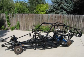
Suspension is done
(12 hours in 3 days, 25.5 hours total)
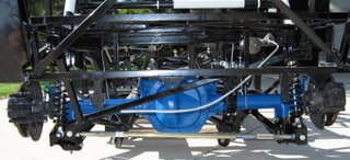
 The suspension is complete. The 3-link rear was interesting, because the FFR instructions are pretty poor. Fortunately, a lot of guys have put pictures of their builds online, so I was able to find some photos that helped me figure out where everything goes. I think everything is together, except that I'll need to swap out the rear lower control arm bolts.
FFR sent me the wrong bolts for the rear LCA. The donor bolts are 100mm, but that's not long enough for the rear brackets on the 3-link. So FFR includes 110mm bolts. Unfortunately, in my kit, what they included was 90mm bolts. Folks on the FFCobra forums complain that even 110mm isn't really enough, and you should use 120mm. Anyone ever try to find Class 10.9 120mm M12 bolts, in Utah, on a Sunday? Not gonna happen. So I just got a couple of 3/8" bolts to hold the arms in place while I completed the rest of the rear end, and I'll swap them for the correct bolts later.
I put the steering rack in, because I was thinking that it would be nice to have steerable wheels. But I found something troublesome. The SN95 spindles that I got with the Cobra brakes seem to have a bump-steer stud mounted. So I have to figure out either how to use it or how to get it out. Either one seems a little tricky right now. I suppose I'll consult the forums for some advice.
 The suspension is complete. The 3-link rear was interesting, because the FFR instructions are pretty poor. Fortunately, a lot of guys have put pictures of their builds online, so I was able to find some photos that helped me figure out where everything goes. I think everything is together, except that I'll need to swap out the rear lower control arm bolts.
FFR sent me the wrong bolts for the rear LCA. The donor bolts are 100mm, but that's not long enough for the rear brackets on the 3-link. So FFR includes 110mm bolts. Unfortunately, in my kit, what they included was 90mm bolts. Folks on the FFCobra forums complain that even 110mm isn't really enough, and you should use 120mm. Anyone ever try to find Class 10.9 120mm M12 bolts, in Utah, on a Sunday? Not gonna happen. So I just got a couple of 3/8" bolts to hold the arms in place while I completed the rest of the rear end, and I'll swap them for the correct bolts later.

I put the steering rack in, because I was thinking that it would be nice to have steerable wheels. But I found something troublesome. The SN95 spindles that I got with the Cobra brakes seem to have a bump-steer stud mounted. So I have to figure out either how to use it or how to get it out. Either one seems a little tricky right now. I suppose I'll consult the forums for some advice.

Thursday, August 31, 2006
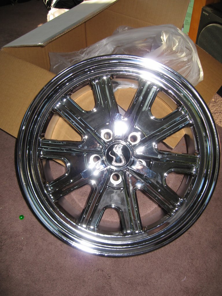
Wheels
(2 hours the last two days, 13.5 hours total)
I got my wheels from Rev Wheel in Riverside. I'm using the "340 Cobra" which is a rough Halibrand replica. The wheels were $150 each for 17" x 9" in chrome, including the fake spinners with snakes. I think they look pretty good.
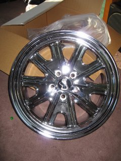 Next up on the purchase list is tires. I've heard good things about the Potenza RE050As, so I'm thinking I'll go with those. Other major purchases still to come are the iSquared electrical system and an AC unit from North Racecars.
Latest work has proceeded smoothly. I opened up my rear end and pulled out the axles. Dropped one of the c-clips down into the depths, but I think I can get it out when I change the oil. My new ball joint separator tool works wonders, so my spindle adapters are painted and reinstalled, and properly aligned this time.
Unfortunately, I realized I need the spindle-to-strut bolts from the Mustang. My spring compressors won't go on the Mustang springs, so I have to figure out another way to protect myself from explosive decompression when I remove the strut. I'm still thinking on this one.
Subscribe to:
Posts (Atom)